1. The Lithium Revolution in Pakistan: Why Tubular Batteries Are Becoming Obsolete
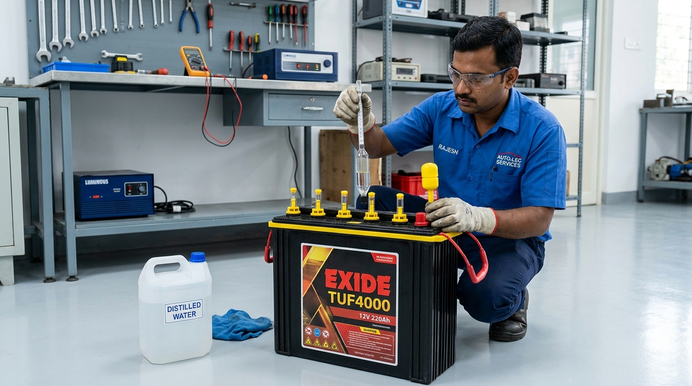
For more than a decade, Pakistani homeowners and businesses navigating chronic load shedding relied almost universally on flooded lead-acid and deep-cycle tall tubular batteries (such as Phoenix, AGS, Osaka, and Daewoo). While tubular batteries provided acceptable short-term backup, their fundamental electrochemical limitations have created immense frustration: a shallow usable Depth of Discharge (DoD limited to 50 percent to prevent permanent sulfation), dismal round-trip energy efficiency (only 70 to 75 percent, wasting one-quarter of all solar charging energy), frequent distilled water top-ups, hazardous acid fumes, and a brief operational lifespan of only two to three years before capacity collapses.
In 2026, the energy storage landscape in Pakistan has fundamentally shifted toward Lithium Iron Phosphate (LiFePO4 or LFP) chemistry. Offering an extraordinary cycle life of 6,000 to 8,000 cycles at 80 percent Depth of Discharge (translating to a 15-year operational lifespan), 95+ percent round-trip efficiency, zero maintenance, and complete immunity to thermal runaway, LiFePO4 has become the premier choice for hybrid solar installations. However, unlike robust lead-acid batteries that can tolerate crude over-charging, lithium cells are extraordinarily delicate electrochemical units. Connecting raw lithium cells directly to an inverter without an intelligent controller will lead to rapid cell swelling, irreversible internal short-circuits, and complete pack destruction.
The unsung brain safeguarding every lithium battery pack is the Battery Management System (BMS). In this engineering deep-dive, BillsOnlinePk explores the sophisticated electronic architecture of lithium BMS modules, details step-by-step communication pairing with major inverters, and demonstrates how proper BMS configuration doubles battery longevity.
Golden Engineering Rule: Never operate a 48V LiFePO4 battery pack in simple "Voltage Mode" (USE setting) if your inverter and battery support closed-loop digital communication (CAN or RS485). Closed-loop communication allows the battery to dynamically command charging voltage and current millisecond by millisecond, preventing cell over-voltage tripping.
2. Anatomy of a Battery Management System: Microcontrollers, Shunts & Solid-State Switches
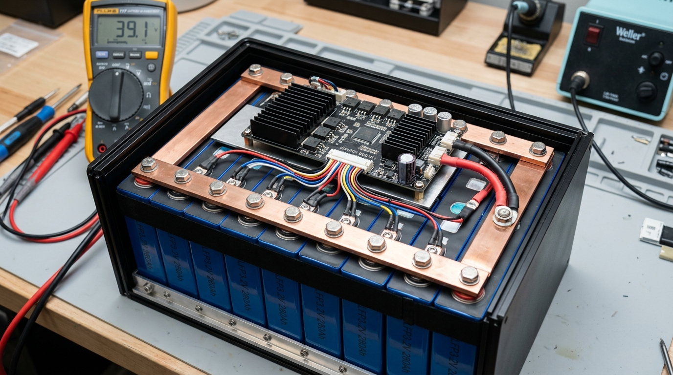
A standard 48V nominal LiFePO4 battery pack consists of 16 individual prismatic cells connected in series (commonly designated as a 16S configuration, producing 51.2V nominal). The BMS is a specialized electronic motherboard mounted directly inside the battery enclosure, consisting of four primary subsystems:

- Microcontroller & Analog Front End (AFE): High-precision 16-channel ADCs monitor the exact voltage of every individual cell in the 16S string with millivolt accuracy (down to ±1 mV). If even one cell reaches 3.65V while other cells remain at 3.40V, the AFE instantly signals the microcontroller to halt charging.
- High-Current Solid-State MOSFET Array: A bank of low-resistance N-channel power MOSFETs (or heavy-duty bidirectional magnetic contactors) positioned on the main negative or positive power rail. These switches can disconnect full charging or discharging currents (typically 100A to 200A continuous) within less than 2 milliseconds if a catastrophic short-circuit or severe under-voltage condition is detected.
- High-Precision Current Shunt: A calibrated low-resistance manganin alloy shunt resistor that measures instantaneous current entering and leaving the pack. By integrating current over time (Coulomb counting), the BMS computes the true, accurate State of Charge (SoC percentage) and State of Health (SoH).
- Thermal Sensor Array: Multiple NTC thermistor probes bonded directly to the physical aluminum casing of the cells and the MOSFET heat sink. The BMS enforces rigid temperature cutoffs: halting charging if temperatures drop below 0°C (preventing lethal lithium plating) or rise above 55°C (preventing thermal degradation).
3. Closed-Loop Inverter Communication: CAN Bus vs RS485 Protocol Handshake
In a properly engineered hybrid solar system, the inverter and the lithium battery do not operate as isolated devices. Instead, they engage in continuous, high-speed digital dialogue across a shielded twisted-pair communication cable (RJ45 patch cable) utilizing either the CAN Bus (Controller Area Network) or RS485 protocol.
During closed-loop operation, the BMS broadcasts real-time telemetry packets to the inverter every 500 milliseconds, transmitting the following critical parameters:
- Charge Current Limit (CCL): The maximum charging current the battery can safely absorb. If the pack is 90% full or approaching thermal limits, the BMS commands the inverter: "Reduce charging current from 60A to 10A immediately."
- Discharge Current Limit (DCL): The maximum instantaneous load the battery can deliver without cell voltage sag.
- Charge Voltage Limit (CVL): The precise bulk/absorption voltage target (typically 56.8V for a 16S pack).
- Real-Time State of Charge (SoC %): The exact calibrated battery percentage displayed directly on the inverter’s primary LCD screen.
| Communication Protocol | Standard Transmission Baud Rate | RJ45 Pinout Configuration | Typical Compatible Inverters in Pakistan |
|---|---|---|---|
| CAN Bus (Preferred Standard) | 250 kbps / 500 kbps | Pin 4 (CAN-H), Pin 5 (CAN-L), Pin 2/7 (Ground) | Deye, Sunsynk, Growatt (SPH), GoodWe, Victron, Solis |
| RS485 Protocol | 9600 bps / 19200 bps | Pin 1 (RS485-B), Pin 2 (RS485-A), Pin 8 (Ground) | Inverex (Nitrox/V-View), Voltronic, Knox, Crown, Phocos |
4. Closed-Loop BMS Communication vs Open-Loop Voltage Mode (USE Setting)
Many local Pakistani electricians, lacking formal training in industrial communication protocols, configure hybrid inverters using generic "User-Defined Voltage Mode" (USE setting). In this open-loop mode, the communication cable is omitted entirely, and the inverter guesses the battery's state of charge purely based on total terminal voltage.
Why is Voltage Mode dangerous for LiFePO4 batteries? The open-circuit voltage discharge curve of lithium iron phosphate is extraordinarily flat: a cell at 80% charge sits at 3.32V, while a cell at 20% charge sits at 3.28V—a variance of only 0.04 Volts! An inverter attempting to gauge battery percentage by voltage alone will wildly fluctuate, falsely reporting 100% full when heavy loads stop, or prematurely shutting down loads while 40% usable energy remains in the cells.
| Operational Parameter | Closed-Loop BMS Communication (CAN/RS485) | Open-Loop Voltage Mode (USE Setting) | Impact on System Health |
|---|---|---|---|
| State of Charge (SoC) Accuracy | ± 1.0% (Precise Coulomb counting) | ± 25% to 40% (Crude voltage guessing) | Closed-loop prevents sudden unexpected blackouts. |
| Cell Over-Voltage Protection | Dynamic throttling prevents high-cell spikes | Inverter forces fixed amps; single cell trips BMS! | Eliminates annoying sudden battery disconnects. |
| Battery Lifespan & Degradation | Full 6,000+ cycles achieved | Degrades in 2,500 - 3,500 cycles due to cell stress | Doubles the financial payback period of your battery! |
| Warranty Compliance | 100% manufacturer warranty valid | Many brands void warranty if operated in USE mode | Protects your high-value capital investment. |
5. Cell Balancing Mechanics: Active Balancers vs Passive Bleed Resistors
Over hundreds of charge-discharge cycles, slight manufacturing differences in internal resistance and temperature gradients across the battery pack cause individual cells to drift apart in voltage. If Cell #1 reaches 3.65V while Cell #16 is only at 3.35V, charging must cease, leaving the pack partially empty. To correct this, the BMS employs cell balancing:
- Passive Balancing (Resistive Bleeding): The standard method in entry-level BMS boards (such as Daly, JBD, and generic server-rack batteries). When any cell exceeds a balancing threshold (typically 3.40V), a tiny SMD transistor switches a small bleed resistor (typically 30mA to 60mA current) across that high cell, dissipating the excess energy as localized heat.
- Limitation: A tiny 50mA bleed current takes hundreds of hours to correct a severe cell voltage gap (e.g., a 150mV imbalance on a 100Ah cell requires over 300 hours of continuous balancing!).
- Active Balancing (Capacitive / Inductive Energy Transfer): Found in premium BMS units (such as PACE, Seplos, JK BMS, and Neey). Active balancers do not waste energy as heat; instead, high-frequency flyback transformers or switched supercapacitors physically transfer excess electrical charge from the highest-voltage cell directly into the lowest-voltage cell at high current (1.0A to 5.0A).
- Advantage in Pakistan: Rapidly balances severely drifted packs within 2 to 3 charge cycles, recovering up to 15 percent of lost usable storage capacity.
6. Critical Voltage Limits: Over-Charge (3.65V), Under-Voltage (2.50V) & Thermal Cutoffs
To configure your inverter and monitor your BMS application accurately, commit the following critical LiFePO4 cell thresholds to memory:
| Cell Condition / State | Single Cell Voltage Threshold | 16S Battery Pack Total Voltage | BMS Action / Recommendation |
|---|---|---|---|
| Absolute Maximum (Over-Voltage Alarm) | 3.65 Volts | 58.4 Volts | BMS cuts off charging instantly to prevent cell swelling. |
| Recommended Bulk / Absorption Target | 3.50 - 3.55 Volts | 56.0 - 56.8 Volts | Optimal charging limit; delivers 99% charge with zero cell stress. |
| Recommended Float Voltage Target | 3.35 - 3.38 Volts | 53.6 - 54.0 Volts | Maintains full charge without keeping cells at high-voltage stress. |
| Nominal Resting Voltage (50% SoC) | 3.28 - 3.30 Volts | 51.2 - 52.8 Volts | Standard mid-point operational plateau. |
| Recommended Low-Voltage Cutoff | 3.00 - 3.05 Volts (15% SoC) | 48.0 - 48.8 Volts | Stops discharge; preserves reserves for emergency load shedding. |
| Absolute Minimum (Under-Voltage Trip) | 2.50 Volts (0% SoC) | 40.0 Volts | BMS disconnects load completely; prevents copper dissolution. |
7. Multi-Battery Parallel Clustering: DIP Switch Addressing & Master-Slave Wiring
When expanding storage capacity by connecting two, three, or four 48V server-rack batteries in parallel to increase capacity from 100Ah (5 kWh) to 400Ah (20 kWh), installers must properly configure the multi-pin DIP Switches (Dual In-line Package switches) on each battery front panel:

- Master Battery (Address 1): The primary battery that communicates directly with the hybrid inverter via the main CAN/RS485 port. Set DIP switch binary address to 1 (Switch 1 ON, Switches 2, 3, 4 OFF).
- Slave Batteries (Address 2, 3, 4...): Subsequent batteries connect to each other in a daisy-chain link via secondary RS485 communication ports (Port B to Port A).
- Battery #2: Set DIP to Address 2 (Switch 2 ON, others OFF).
- Battery #3: Set DIP to Address 3 (Switches 1 and 2 ON, others OFF).
- Battery #4: Set DIP to Address 4 (Switch 3 ON, others OFF).
- DC Busbar Paralleling: Never daisy-chain heavy DC power cables from battery terminals directly to each other! Instead, run equal-length 35mm² or 50mm² copper cables from each battery module to a central copper distribution busbar. This ensures perfectly balanced current sharing across all packs.
8. Diagnosing Common BMS Trips: Red Alarm LED, Cell Imbalance & Communication Loss
If your lithium battery displays a solid or flashing red "ALM" (Alarm) indicator, consult this diagnostic matrix before panicking:
- "COMM FAULT" on Inverter Screen: Indicates communication cable pinout mismatch or wrong protocol selection in inverter menu (e.g., selecting "Pylontech" when the battery uses "PACE" or "Growatt" protocol). Check the RJ45 pin crimping order: verify that CAN-High (Pin 4) and CAN-Low (Pin 5) match your inverter’s specification sheet.
- BMS Trips During Final 5% of Charging: One individual cell has drifted high and breached 3.65V while total pack voltage is still only 54.5V! Lower the inverter bulk charge voltage target to 55.2V for several days. This allows the internal cell balancer sufficient time to bleed down the runaway cell.
- Battery Disconnects Instantly When Heavy Load Starts: Indicates that one weak or degraded cell is sagging below the 2.50V low-voltage cutoff under high load (such as a 1.5-ton inverter AC starting). Connect a laptop via RS485-to-USB adapter and launch the BMS monitoring software (such as PBMS Tools or BMS Test) to inspect individual cell voltages under load.