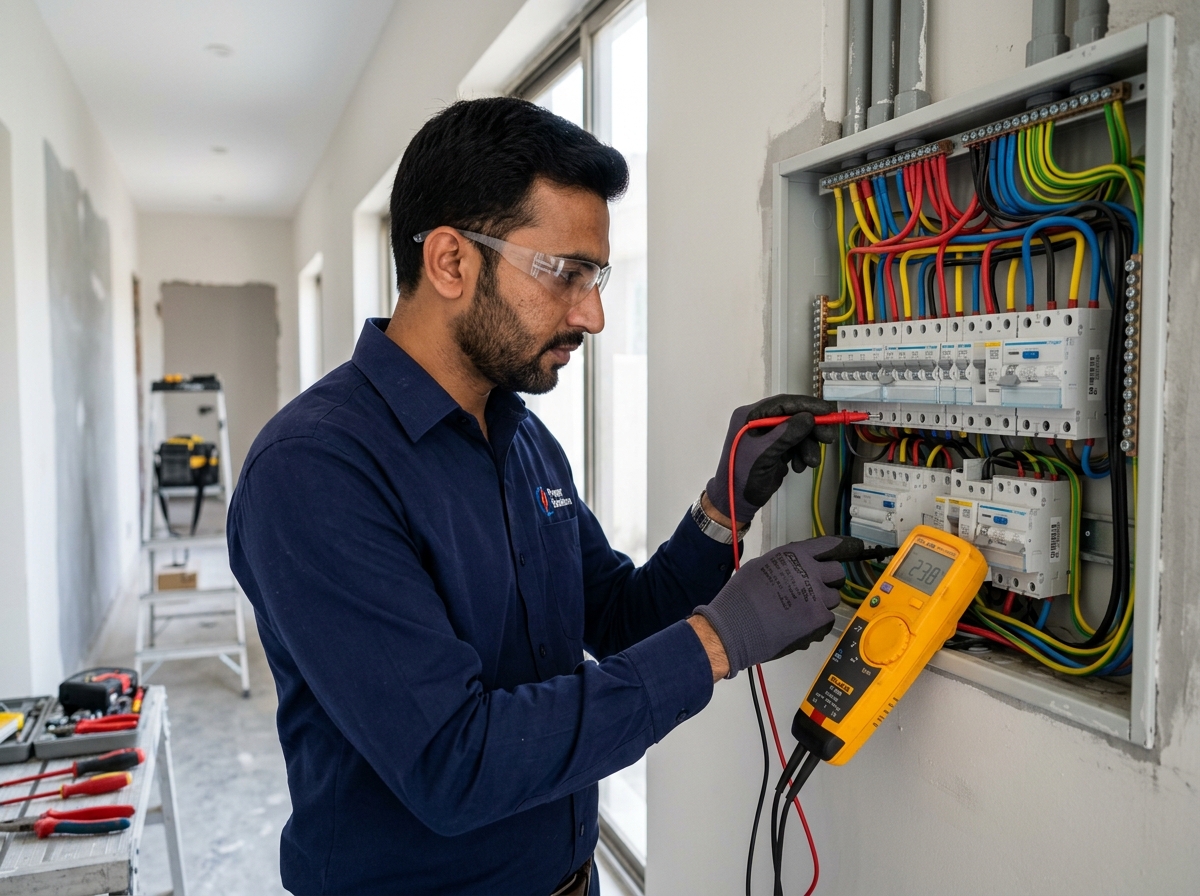
1. Why Solar Arrays Are Lightning Magnets & Fire Hazards in Pakistan
Across Pakistan, tens of thousands of residential, commercial, and industrial rooftop solar installations are operating in an alarmingly precarious state of electrical vulnerability. Elevated on rooftop perches to clear parapets and water overhead tanks, massive metallic solar mounting structures constructed from galvanized iron or aluminium alloy form the highest conductive elevation point on modern Pakistani homes. During monsoon thunderstorms in July and August, or severe pre-monsoon convective storm fronts across Punjab, Khyber Pakhtunkhwa, and Sindh, these elevated metallic structures act as prime targets for direct cloud-to-ground lightning strikes and high-voltage atmospheric electrostatic induction.
A direct lightning strike carries peak electrical discharge currents ranging from 30,000 to over 100,000 Amperes, generating transient voltages exceeding tens of millions of Volts. Without an ultra-low-impedance, dedicated direct discharge path to the earth mass, this colossal electrical surge instantly vaporizes solar photovoltaic silicon wafer junctions, arcs across bypass diodes, shatters inverter power electronics (IGBT modules and micro-controllers), and travels along domestic distribution conduits, sparking catastrophic structural fires and lethal electric shock hazards for household occupants.
Furthermore, even in the complete absence of direct lightning strikes, ungrounded solar arrays accumulate immense static electrical charges from dust storms, dry desert winds, and atmospheric friction. In dry regions such as Bahawalpur, Dera Ghazi Khan, Quetta, and Sukkur, static potential on ungrounded solar frames regularly builds to 4,000 to 8,000 Volts. When a human technician touches the frame during routine panel cleaning, the discharge can trigger severe electrical shock or cause the technician to fall from the elevated roof. In this engineering guide, BillsOnlinePk outlines the strict technical protocol required to design, construct, and maintain an IEEE-compliant earthing and lightning protection infrastructure for solar installations in Pakistan.
Critical Safety Warning: Never connect your solar mounting structure or lightning arrester to your home’s existing WAPDA distribution neutral wire or internal plumbing water pipes! Doing so creates an extreme electrocution hazard across all household taps and metal appliances during an electrical storm. A solar installation requires dedicated, physically isolated earth pits.
2. The Three Mandatory Independent Earthing Circuits: AC, DC & Lightning Arrester
A widespread and hazardous shortcut committed by unqualified local electricians in Pakistan is "loop earthing," where the lightning arrester, the solar panel aluminium frames, the inverter DC enclosure, and the home's AC distribution board are all clamped onto a single thin copper wire tied to a rusty iron water pipe. In photovoltaic engineering, this practice violates international safety standards (IEC 62305, NFPA 780, and IEEE 142) and is explicitly rejected during official DISCO net-metering site inspections.
A compliant, high-reliability solar photovoltaic installation demands three completely independent, physically segregated earthing circuits, each terminating in its own dedicated grounding pit:
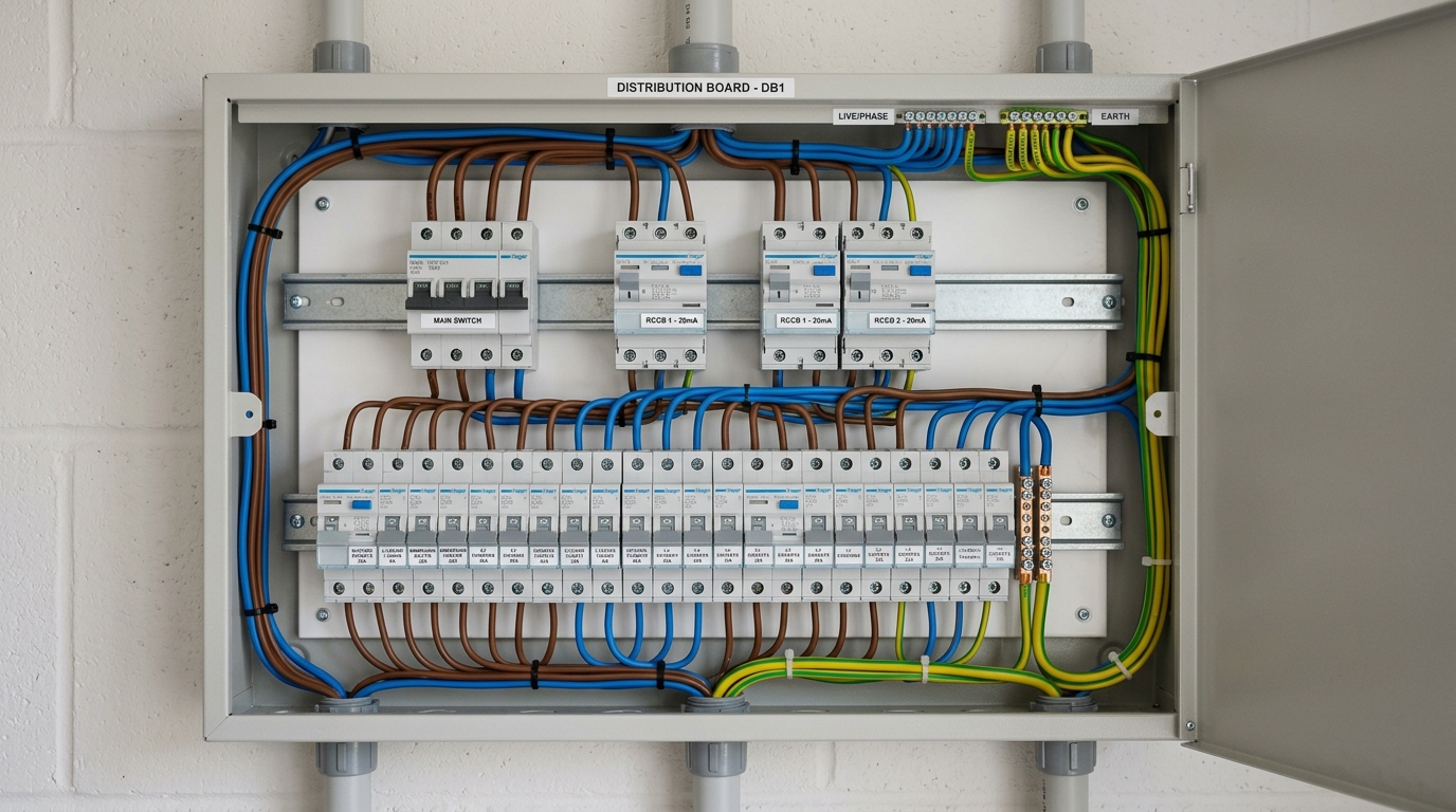
| Earthing Circuit | Protected Equipment & Terminations | Recommended Conductor Specification | Target Resistance | Purpose & Discharge Behavior |
|---|---|---|---|---|
| 1. DC Earthing Circuit | Solar panel aluminium module frames, elevated metallic mounting structure, and inverter DC negative chassis. | 16mm² or 25mm² multi-strand bare or green PVC insulated copper wire. | < 5.0 Ohms | Drains continuous static charges, frame leakage currents, and DC high-voltage transient surges. |
| 2. AC Earthing Circuit | Inverter AC output ground terminal, AC breaker distribution board (DB box), and surge protector ground bar. | 10mm² or 16mm² multi-strand green/yellow copper conductor. | < 2.0 Ohms | Clears internal 230V/400V short-circuits, trips RCCB breakers, and eliminates touch voltage shocks. |
| 3. Lightning Arrester (LA) Circuit | Rooftop Copper Franklin Rod or Early Streamer Emission (ESE) lightning terminal. | 25mm × 3mm pure copper flat tape or 50mm² stranded copper down-conductor. | < 5.0 Ohms (Ideal < 1 Ohm) | Safely intercepts and channels mega-ampere atmospheric lightning strikes directly into deep earth. |
The physical separation distance between the Lightning Arrester earth pit and the AC/DC electrical earth pits must be maintained at a minimum of 3 to 5 meters (10 to 16 feet). This spatial isolation prevents dangerous ground potential rise (GPR) back-feeding into the domestic wiring during a mega-ampere lightning strike.
3. Chemical Earthing (Bentonite/Marconite) vs Traditional Salt & Charcoal Pits
The electrical efficacy of any grounding electrode depends fundamentally on the soil resistivity (ρ, measured in Ohm-meters) of the surrounding earth. In Pakistan, soil conditions vary dramatically: from highly conductive alluvial clay in central Punjab (low ρ = 15 to 30 Ω·m) to high-resistivity dry sandy soils in southern Punjab and Sindh (60 to 150 Ω·m), and rocky limestone terrain in Islamabad, Rawalpindi, and Balochistan (200 to 1,000+ Ω·m).
For decades, Pakistani electricians relied on traditional "Namak aur Koyle ka Gaddha" (Salt and Charcoal earthing pits). While inexpensive initially, traditional salt-charcoal pits suffer from severe, fatal flaws:
- Aggressive Galvanic Corrosion: Sodium chloride (common salt) dissolves into corrosive chloride ions that eat away copper and galvanized steel rods within 24 to 36 months, reducing an earthing rod to brittle rust.
- Leaching & Periodic Desiccation: In Pakistan's scorching summers, subsoil moisture evaporates. Soluble salt leaches out into surrounding soil layers, causing pit resistance to skyrocket from 4 Ohms to over 80 Ohms within two years unless water is manually poured down a pipe weekly.
Consequently, international electrical codes and modern Pakistani solar EPC contractors mandate Chemical Earthing utilizing advanced Carbon-based Ground Enhancing Compounds (such as Marconite, Bentonite clay, or San-Earth):
| Performance Feature | Traditional Salt & Charcoal Pit | Advanced Chemical Earthing Compound | Engineering Assessment |
|---|---|---|---|
| Operational Lifespan | 2 to 4 Years (Corrodes rapidy) | 20 to 25 Years (Zero maintenance) | Chemical earthing matches the 25-year lifespan of solar panels. |
| Moisture Retention | Requires regular weekly water pouring | Hygroscopic; absorbs ambient moisture naturally | Chemical compound never dries out even during 48°C heatwaves. |
| Corrosiveness to Copper | Extremely high (Pitting corrosion) | Non-corrosive, inert pH buffer (pH 7.0 - 8.5) | Protects copper bonding layer indefinitely. |
| Resistance Stability | Fluctuates wildly with seasonal weather | Rock-solid constant resistance year-round | Guarantees permanent compliance with NEPRA standards. |
| Installation Material Cost | PKR 12,000 - 18,000 per pit | PKR 25,000 - 35,000 per pit | Higher initial investment, but zero recurrent maintenance expenses. |
4. Grounding Electrodes: Copper-Bonded Steel Rods (16mm) vs GI Pipes
The central grounding electrode is the physical metallic spear driven into the subsoil. In Pakistan's hardware bazaars, contractors are offered three distinct categories of earth rods:
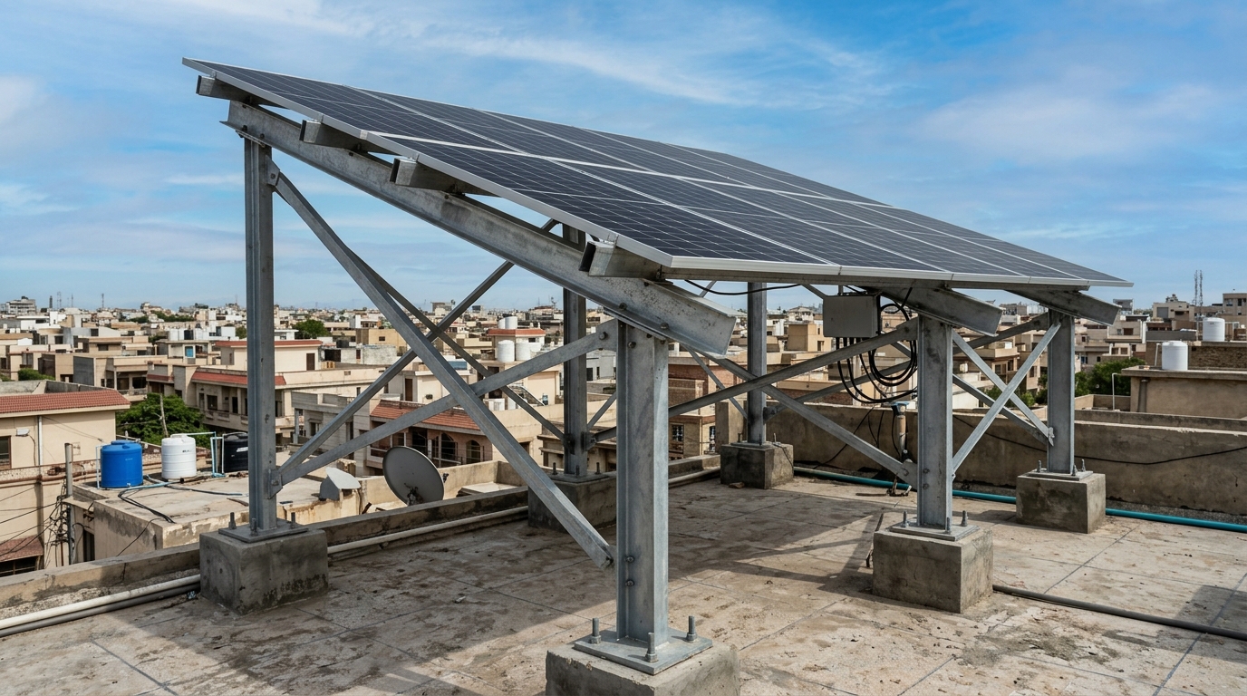
- Copper-Bonded Steel Rods (UL 467 Listed): The gold standard in modern electrical grounding. These electrodes feature a high-tensile carbon steel core (providing immense structural driving rigidity to penetrate rocky soils without bending) molecularly bonded with a continuous outer sheath of 99.9% pure electrolytic copper (minimum thickness of 250 microns / 10 mils). They offer extraordinary electrical conductivity, exceptional mechanical strength, and 30-year resistance to subsoil oxidation.
- Solid Pure Copper Rods: Highly conductive, but extraordinarily expensive and structurally malleable. When technicians hammer a pure copper rod into hard Pakistani clay or rocky subsoil, the rod bends, mushrooms at the head, and fails to penetrate beyond 4 to 6 feet deep.
- Galvanized Iron (GI) Water Pipes: Cheap 1.5-inch or 2-inch hollow GI pipes commonly installed by local plumbers. Zinc galvanizing in subsoil environments oxidizes within 3 to 5 years, leaving bare steel that rusts completely through, severing the ground continuity path.
Specification Recommendation: For residential and commercial rooftop solar installations in Pakistan, insist on minimum 14.2mm or 16mm diameter, 10-foot (3.0 meter) length copper-bonded steel rods, coupled with heavy-duty cast-bronze earthing clamps or permanent exothermic (cadweld) molecular bonds.
5. Fall-of-Potential Earth Resistance Testing with Digital Megger
The only legitimate, scientifically valid method to verify the integrity of an earthing installation is through a Digital Earth Resistance Tester (commonly called an Earth Megger) utilizing the internationally recognized Three-Point Fall-of-Potential Method (IEEE Standard 81):
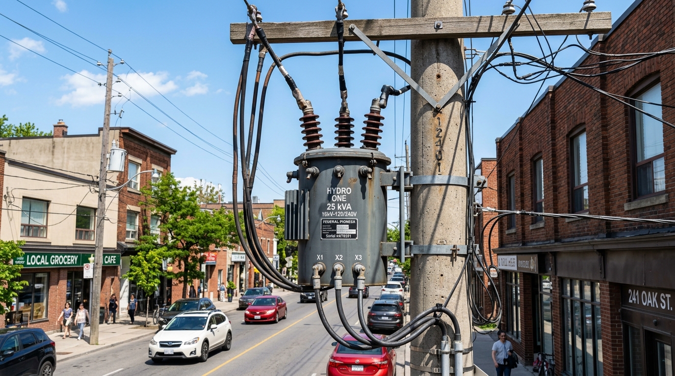
- Electrode Isolation: Disconnect the earthing conductor from the earth pit’s test link or inspection busbar to ensure test currents do not back-feed into the building or solar inverter.
- Auxiliary Spikes Placement: Drive two temporary steel auxiliary ground spikes into straight-line soil:
- Current Probe (C2): Driven into undisturbed soil at a distance of 30 meters (100 feet) from the earth pit electrode under test (E1).
- Potential Probe (P2): Driven directly in a straight line between E1 and C2 at a distance precisely equal to 61.8% of the total distance (i.e., 18.5 meters or 62 feet from E1).
- Measurement: Connect the digital tester terminals (E to pit, P to probe P2, C to probe C2). The tester injects a known low-frequency AC current (typically 128 Hz to avoid 50 Hz power-grid interference) and measures the voltage drop, instantly computing ground resistance in Ohms.
6. Sizing Type I and Type II Surge Protection Devices (SPDs) and Class B+C Arresters
Even with pristine earth pits, transient high-voltage surges generated miles away can enter your home through the overhead WAPDA distribution lines or travel along solar DC string cables. To clamp these microsecond voltage spikes, your solar electrical distribution system requires coordinated Surge Protection Devices (SPDs):
| Surge Protection Category | Location of Installation | Max Discharge Current (I_max) | Voltage Protection Level (U_p) | Function & Defense Barrier |
|---|---|---|---|---|
| Type 1 (Class B) SPD | Main AC Service Entrance / Main Distribution Board | 50 kA - 100 kA (10/350 μs impulse) | < 2.5 kV | First line of defense against direct lightning strikes and heavy utility transformer switching surges. |
| Type 2 (Class C) DC SPD | Solar DC Combiner Box (before inverter DC inputs) | 20 kA - 40 kA (8/20 μs wave) | < 1.5 kV (600V - 1000V DC rated) | Protects inverter MPPT circuits from lightning-induced electromagnetic transients on rooftop strings. |
| Type 2 (Class C) AC SPD | Inverter AC Output Sub-DB Box | 20 kA - 40 kA (8/20 μs wave) | < 1.2 kV (275V - 385V AC rated) | Shields sensitive inverter synchronization electronics from grid-side switching spikes. |
7. IEEE 142 & NEPRA Earthing Standards: Enforcing Under 5 Ohms Resistance
Under the NEPRA Distributed Generation and Net-Metering Regulations 2015 (Standard Operating Procedure Section 4.3), all grid-tied distributed generation installations must comply with strict electrical safety codes before a Net-Metering green meter can be energized. The electrical inspector appointed by the provincial government or the DISCO’s technical inspection committee performs a mandatory pre-commissioning earth resistance audit:
- Residential Solar Systems (≤ 25 kW): Earth resistance must not exceed 5.0 Ohms.
- Commercial & Industrial Systems (> 25 kW to 1 MW): Combined grounding resistance must remain strictly below 1.0 to 2.0 Ohms.
- Lightning Protection Systems (LPS): Dedicated lightning down-conductor earth pit resistance must not exceed 5.0 Ohms (ideally below 2.0 Ohms for high-rise buildings).
If your installer fails to achieve these certified resistance ratings, the DISCO electrical inspector will issue an immediate discrepancy notice, rejecting your net-metering application until the earth pits are re-engineered.
8. Step-by-Step Earth Pit Construction & Inspection Protocol for Pakistani Homes
Follow this master engineering construction checklist to ensure your earth pits perform flawlessly for over 25 years:
- Excavation: Bore an auger hole or dig a vertical trench 8 to 10 inches in diameter to a depth of 10 to 12 feet (3.0 to 3.6 meters) into native subsoil. Never stop at 4 or 5 feet, as upper soil layers dry out completely during summer heatwaves.
- Rod Installation: Drive a 10-foot, 16mm copper-bonded steel rod vertically into the center of the pit. Ensure at least 6 to 8 inches of the rod head remains accessible above the pit bottom for terminal connection.
- Chemical Slurry Preparation: Mix 2 to 3 bags (50 to 75 kg) of high-grade bentonite or carbon-based conductive chemical grounding compound with clean water to form a dense, homogenous slurry.
- Backfilling: Pour the conductive slurry into the bore hole surrounding the entire length of the rod, completely eliminating air pockets. Backfill the top 2 feet with native soil tamped firmly.
- Inspection Chamber: Construct a heavy-duty 12×12 inch brick masonry or pre-cast concrete inspection chamber at ground level with a removable cast-iron or fiber-reinforced plastic (FRP) cover.
- Terminal Connection: Bolt the main 25mm² copper down-conductor onto the rod head using an authentic cast-bronze grounding clamp or exothermic weld. Apply a generous coating of petroleum jelly or antioxidant conductive grease to prevent terminal oxidation.